How To Read Engineering Drawing Ppt
How to Read A Electrical Drawing 1. Reading Technical Drawings Foundations of Manufacturing Dimensioning Systems Four different systems of dimensioning used in US.
Architects scale always reads X 1- 0 For example ½ 1- 0 or 3 1- 0.
How to read engineering drawing ppt. Architects Scales and Sizes 16 Scale Full Size 12 1- 0. Edraw provides all kinds of symbols required in piping and instrumentation diagrams. Read a working or assembly drawing blueprint Represent mechanical components in multiview orthographic.
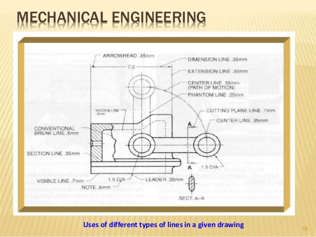
The Engineering Drawing common to all Engineering Trades as per NSQF 1st Semester is the outcome of the collective efforts of experts from Field Institutes of DGT champion ITIs for each of the Sectors and. 19012017 Type of Lines Dimensioning and. Engineering Drawing Lecture 2 Drawing an arc tangent to a given point on the line Steps Microsoft PowerPoint Engineering Drawing Tutorial Ppt PDF Online Free.
12 1 Read as 12 inch on the drawing equals 1 foot on the actual. 38 1 Read as 38 inch on the drawing equals 1 foot on the actual component or system. Mechanical Industrial Engineering.
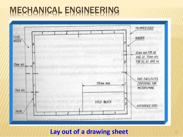
One should strive to develop the skill to produce a rendering that is. It covers several fundamental topics1 The layout of the drawing2 Title block3 First VS. Download Download Engineering drawing tutorial ppt Read Online Read Online Engineering drawing tutorial ppt ME 111.
The Engineering Drawing common to all Engineering Trades is one of the book developed by the Core group members as per the NSQF syllabus. March 14 2018 Engineering drawing tutorial ppt. The first step to read a Piping and Instrumentation Diagram is to know how to read its symbols and shapes in the drawing.
Napkin to a detailed engineering drawing. 23 Full PDFs related to this paper. When the current passes through the lamp it will produce light.
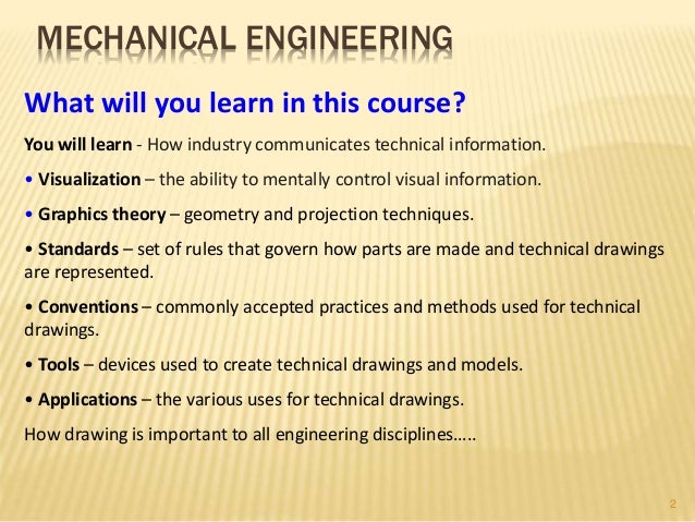
- PowerPoint presentation - Material available on course website Lecture to be done on boardscreen. Identify and Understand Standard Equipment -Instruments. Lean Six Sigma Yellow Belt LSSYB.
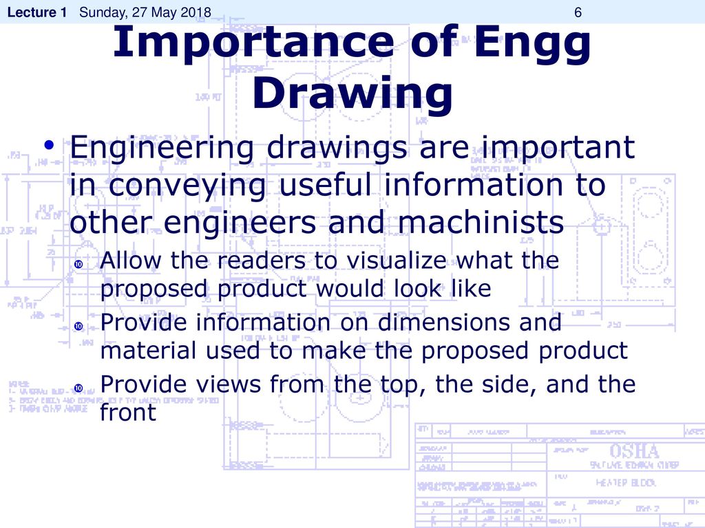
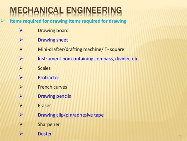
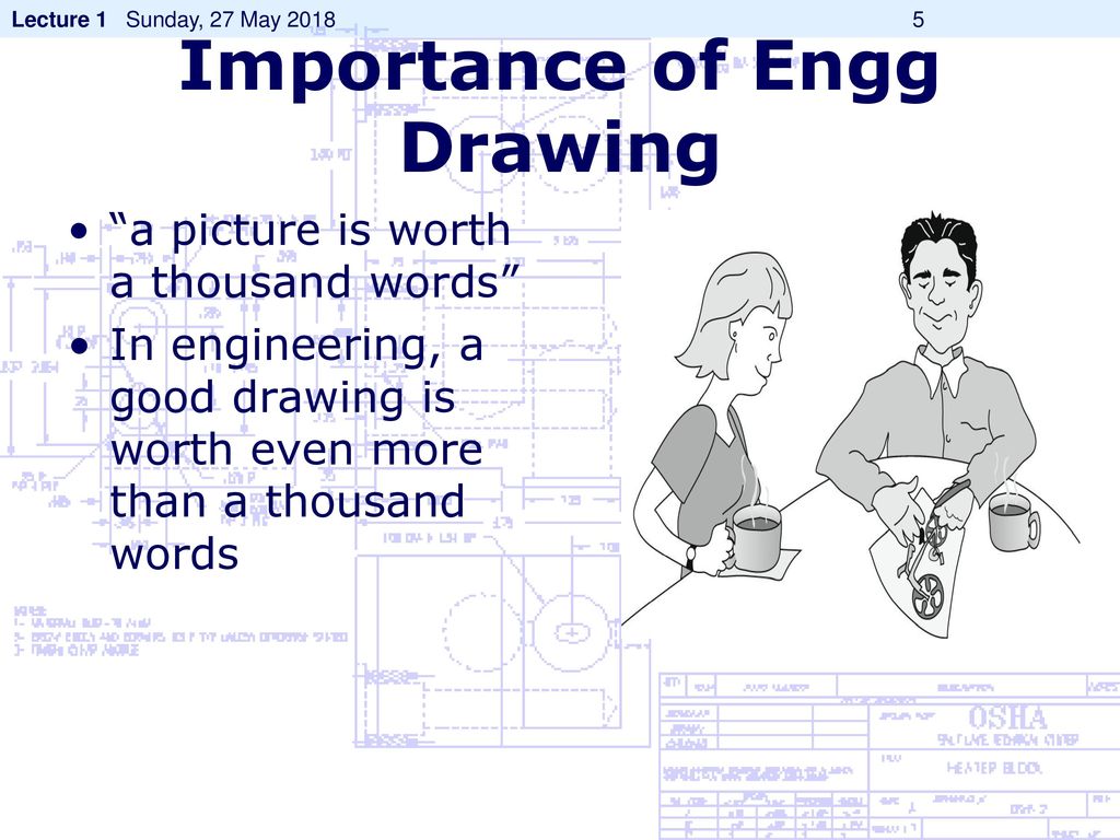
HELLO EVERYONE Created By Govind B Nadare BE In Mechanical Engineering One Year Experience in Bajaj Auto Ltd. The Purpose of Engineering Drawings. As already said such a technical drawing has all the information for manufacturing a part or welding and building an assemblyThe info includes dimensions part names and numbers etc.
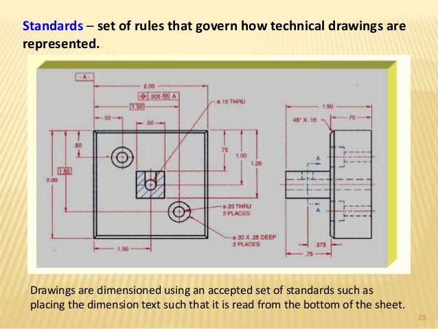
Engineering Drawing WELCOME TO. Drawings are dimensioned using an accepted set of standards such as placing the dimension text such that it is read from the bottom of the sheet. Each part is 1 meter.
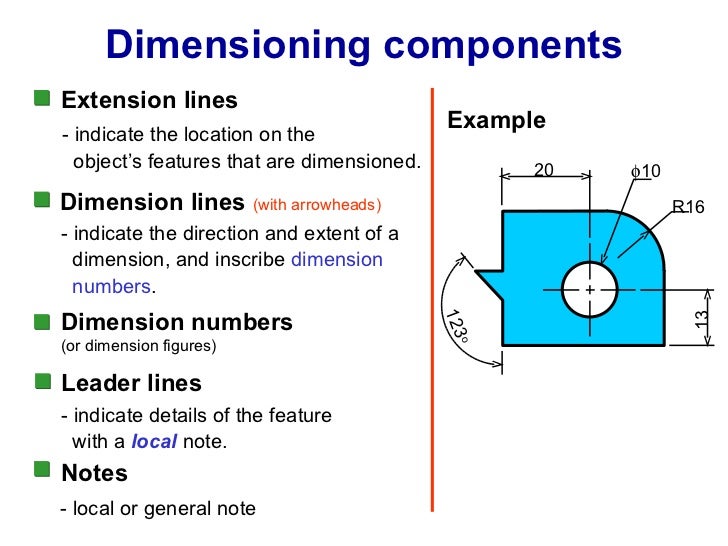
Engineering drawing example Types of Drawings All Drawings Artistic Technical Sketches Diagrams Drawings conceptual design technical technical. FIGURE 21 Use of projection and dimensioning Arrcwheads are drawn open or solid about g mm long I mm wide projection lines are lines and may cross are thin lines 2mm past dimension ine mm gap rowheads should touch projection lines at extremities the dimension are on the outside of projection for smaller Dimension line is drawn parallel to direction ot measurement am placed outside the view. Many Structural Engineering detail drawings are read using the Architects scale.
125 to read up to 4 meters. The engineering drawing is the specification for the component or assembly and. A lamp is usually represented as a circle with a cross inside it.
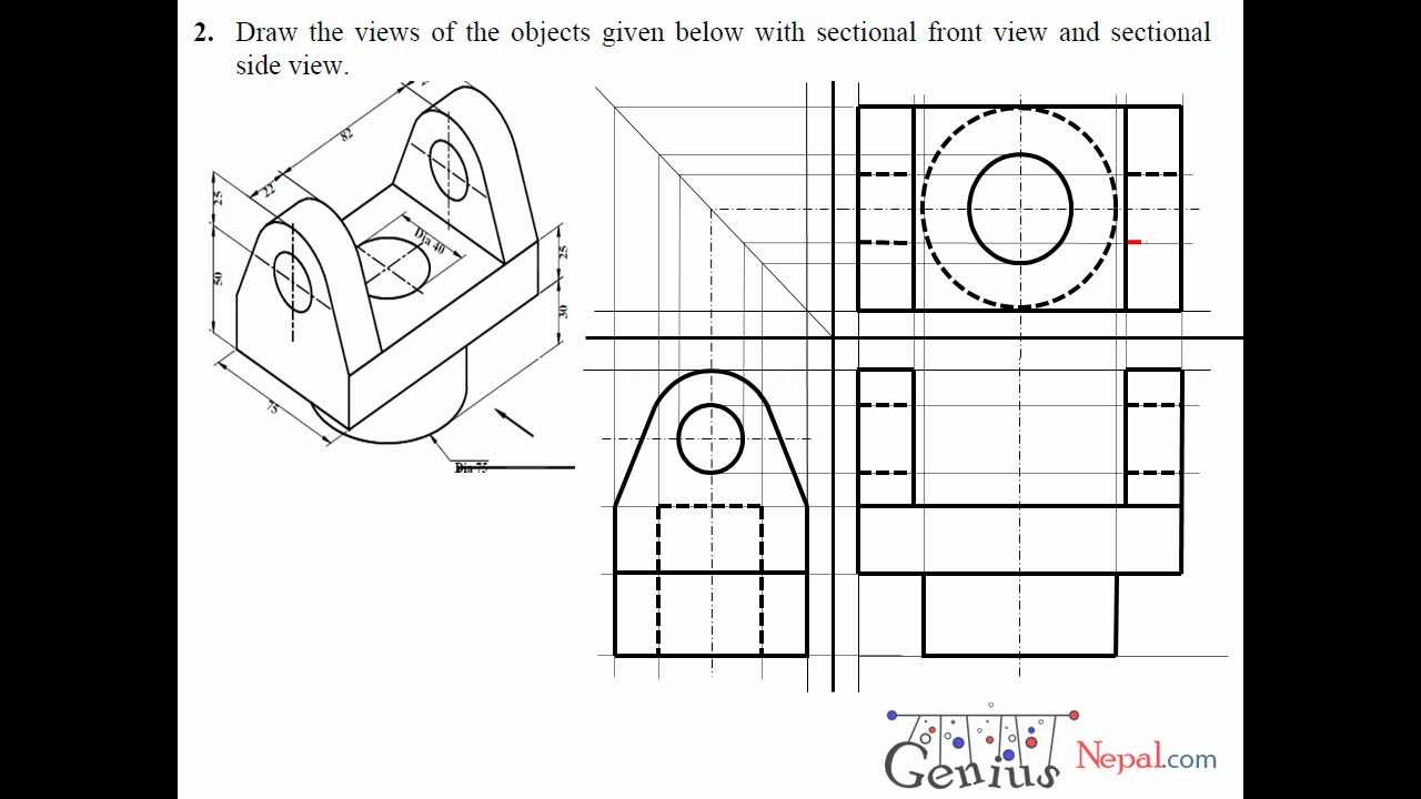
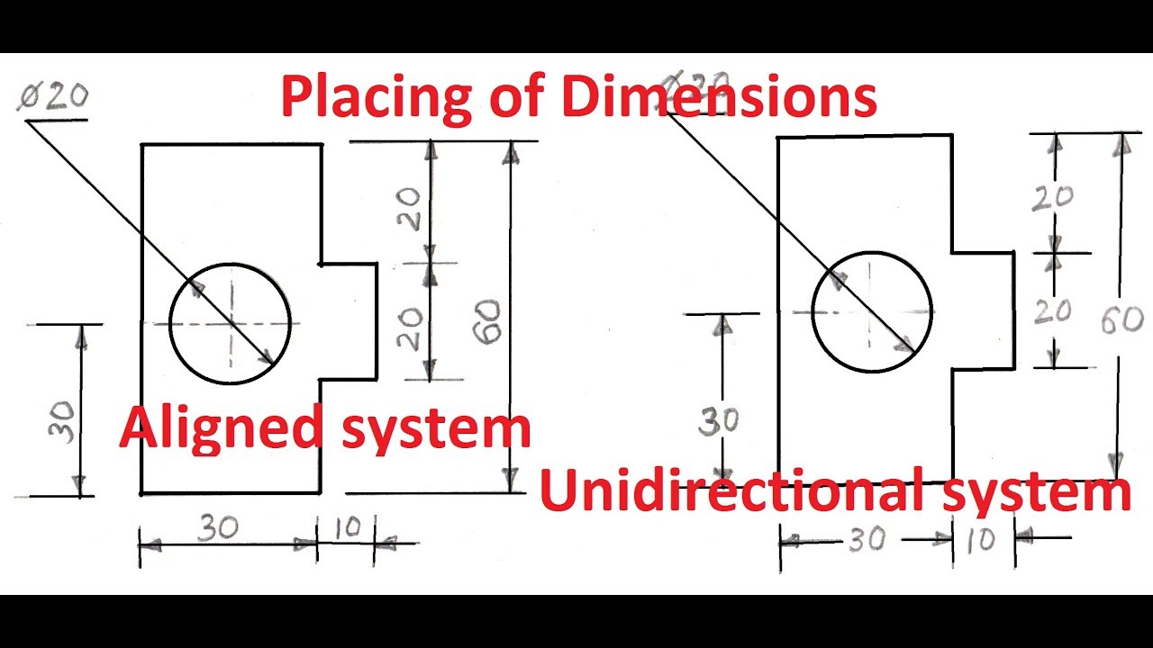
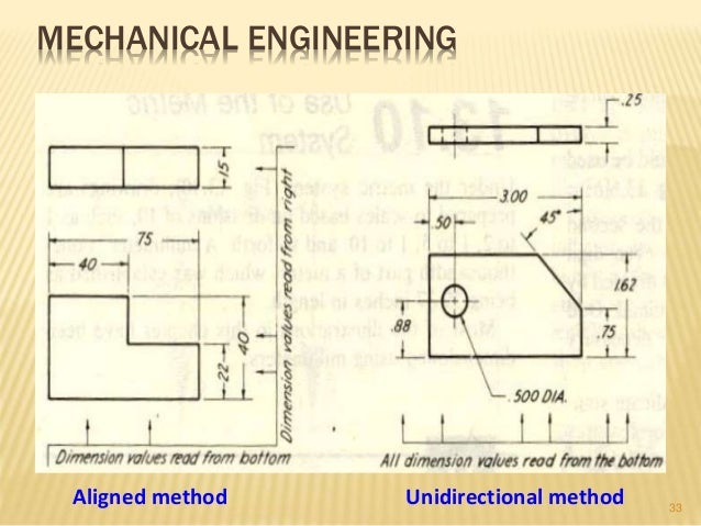
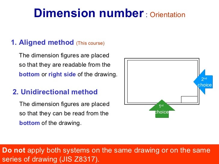
Unidirectional System In the unidirectional system the dimensions are so oriented such that they can be read from the bottom of the drawing. Familiarize with Standardized Electrical Symbols Knowing the meanings of basic electrical symbols in your electrical drawing will help you quickly understand and troubleshooting the circuit. This video discusses the basics of reading engineering drawings.
Course Introduction Types of drawings Engineering also known as production or working drawings. On it show lengths 239 m and 091 m Length of Scale 125 4 100 16 cm Draw a 16 cm long line and divide it into 4 equal parts. Engineering Engineering Drawing Engineering Drawing Presentation Engineering Drawing.
Divide each of these parts in to 10 equal parts to show decimeter 10 cm. Aligned System In the aligned system the dimensions are placed perpendicular to the dimension line in such a way that it may be read from bottom edge or right hand edge of the drawing sheet. Fractional inch Decimal inch Dual.
Drawing is the actual distance or size of the component. So once a manufacturing engineer gets the drawing he can start the production process without a second thought. This is called 38 scale.
Engineering Drawing basicsppt 1. Draw a Vernier scale of RF. Aircraft Drawing and Blueprint Reading.
For example if a component part measures 68 inch on the drawing the actual component measures 2 feet. Waluj Aurangabad Engineering Drawing.